


As grasp scale modeler Dave Platt has mentioned, “A scale mannequin is rarely really completed–you merely cease working in it.” I first take a look at flew my Sopwith Camel with my Zenoah G38 engine absolutely uncovered in that huge radial cowling. So, to assist gown it up, I’ve begun to put in a dummy rotary engine. I hope you discover the strategies concerned fascinating as they can be utilized on any related spherical nosed airplane you is likely to be constructing.
Start line
Balsa USA is a superb supply for all issues WW1 they usually have been providing good molded fiberglass dummy engines for a very long time. I picked up a 9-cylinder molding on the current Rhinebeck Jamboree and wasted no time in getting it detailed out and able to add the Camel’s engine compartment.
Properly molded from a number of layers of fiberglass fabric, the BUSA molding is properly detailed. You’d spend much more time making an attempt to make your individual. That is an older photograph, the one I simply picked up has a pleasant gel coat end on the entrance.
The very first thing to do with any molded fiberglass half is to make use of a grinding wheel and a Moto-tool and take away any sharp edges or areas starved of resin. After this, throw it within the kitchen sink and scrub it with dish washing detergent so you’ll be able to take away any left over parting agent that may nonetheless be on the surfaces.
Right here you see the open finish of the cowling, you will need to use a molded engine that may match correctly. The 1/4-scale BUSA rotary engine is 7 3/4 inches in diameter, an ideal match.
With the cowling eliminated you’ll discover I put in a ballast field stuffed with lead shot and resin proper over the engine. I made it’s dimensions with the usage of a dummy engine in thoughts.
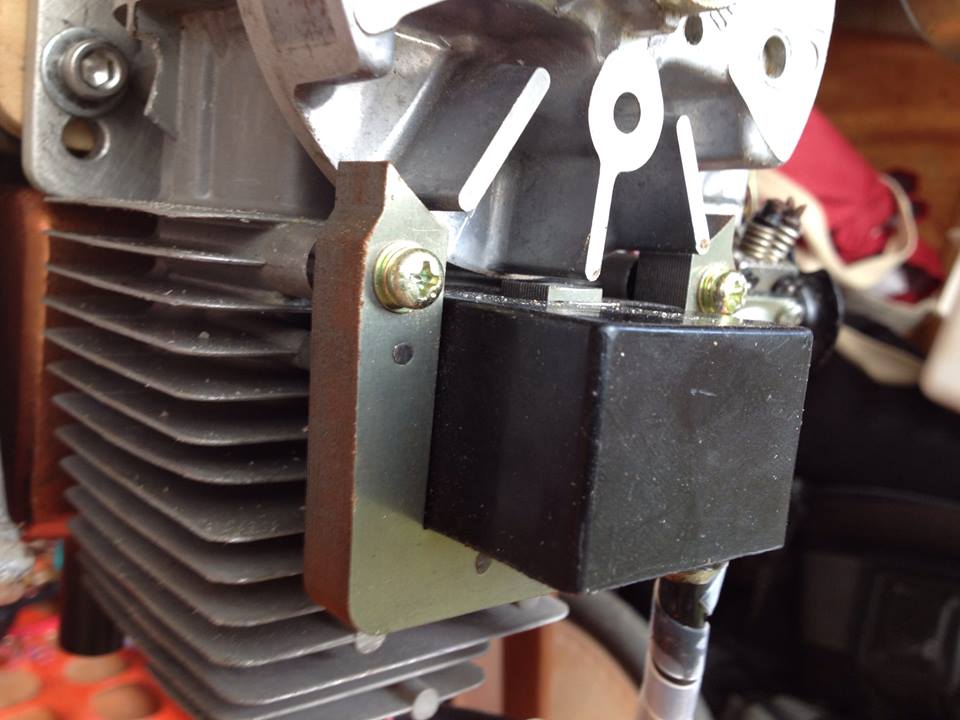
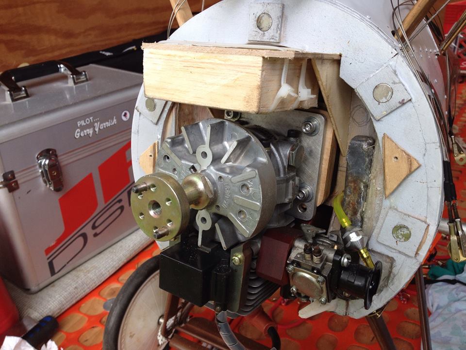
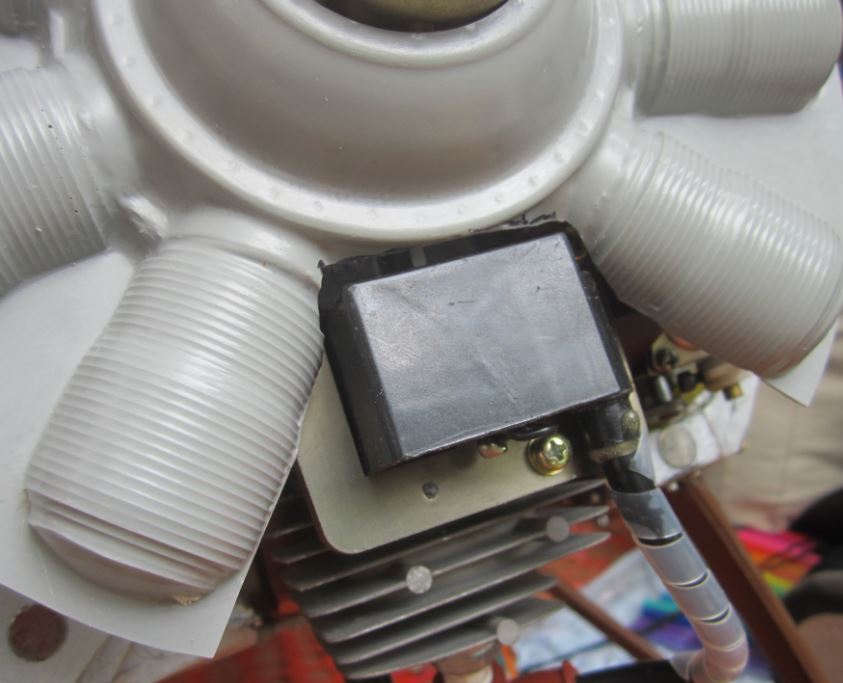
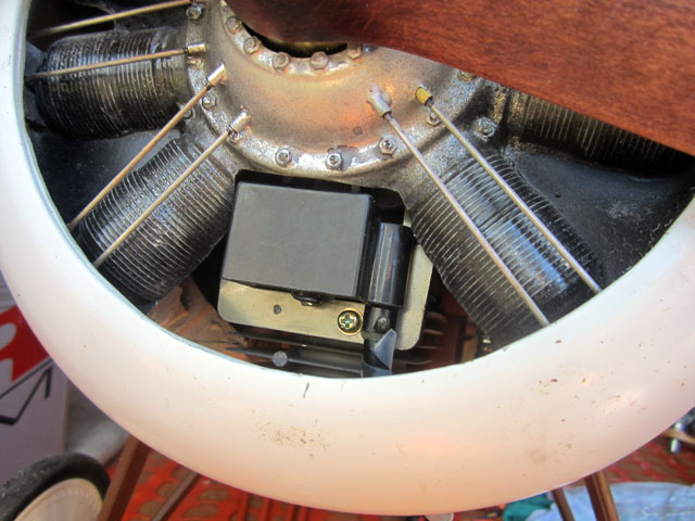
Right here’s the entrance finish of the G38 with it flywheel and magnet for the magneto ignition exhibiting proudly in entrance of the cylinder head. The engine is put in upside-down with the cylinder and muffler each pointing downward. The very first thing to do is to open up the molded engine to clear the ignition block. However extra importantly, the opening can be for cooling airflow to enter the engine compartment.
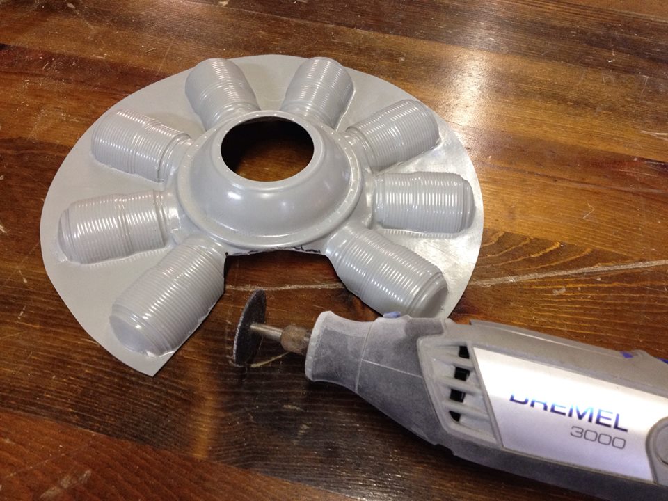
Making the opening is simple with a cutoff disc and a Dremel. I merely eliminated one of many cylinders and opened up the world between the opposite cylinders as proven right here. Additionally, the middle opening for the crankcase, must be sufficiently big to suit over the G-38’s propeller hub.
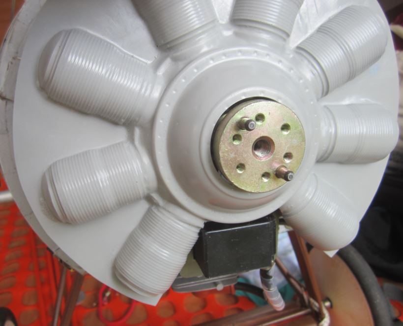
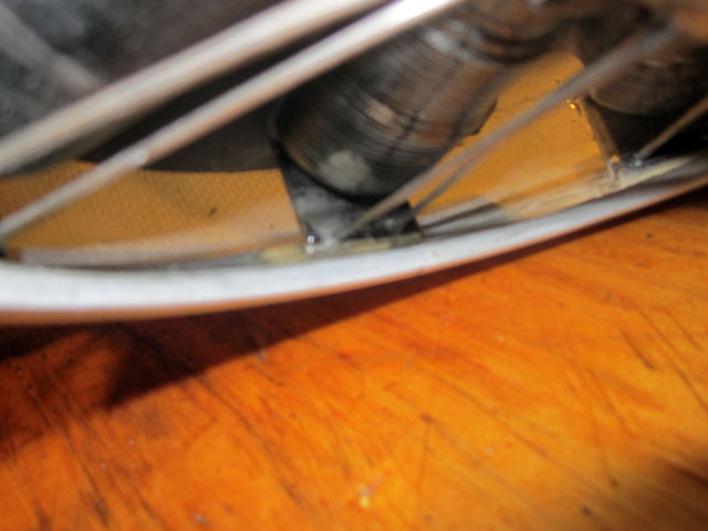
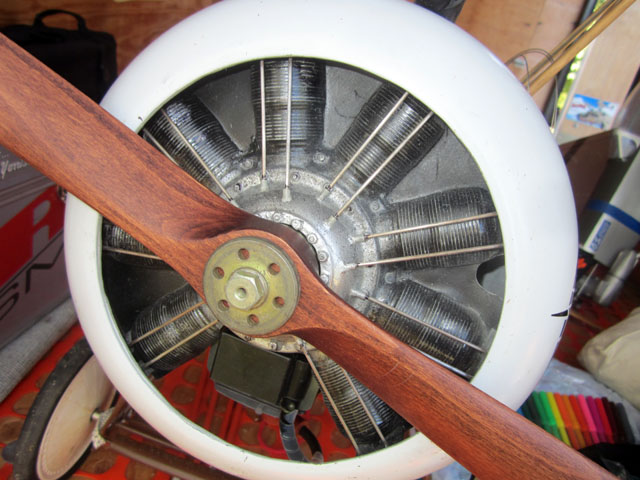
Right here I’m take a look at becoming the molding over the G-38. The opening ought to present about 1/8 inch of clearance throughout so vibration received’t trigger any chaffing of components. You may also see that cylinder is correct within the line of fireside for airflow.
So the molding matches properly centered over the G38 whereas contacting the entrance of the ballast field. One other advantage of the field construction is that it helps channel airflow down towards and across the engine and never up within the empty area in regards to the engine.
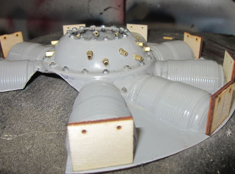
Earlier than portray, I drilled holes and added nuts and screws so as to add element to the engine case. Additionally, I drilled offset holes within the engine case for the bushing (from quick sections of brass tubes), for the pushrods which shall be added later. Medium and Thick ZAP CA glue is used all through. Be mild with the kicker as it may well trigger the glue to foam up, which won’t assist the end.
You may additionally have seen the lite-ply information/helps I glued to the engine molding. These have 1/16 inch holes in them set on the correct spacing to carry the pushrod wires. Right here is the easy reduce job loaded into my laser cutter.
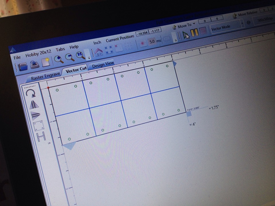
Utilizing my 40W Full Spectrum Laser Passion Laser I used to be in a position to import some easy CAD drawing and reduce out the eight are required for the dummy engine. You may see the lite-ply information plates intimately right here under.
Portray
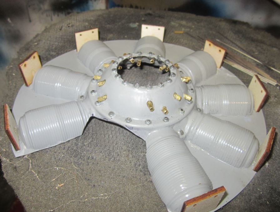
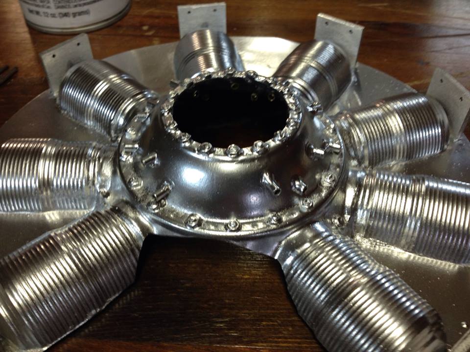
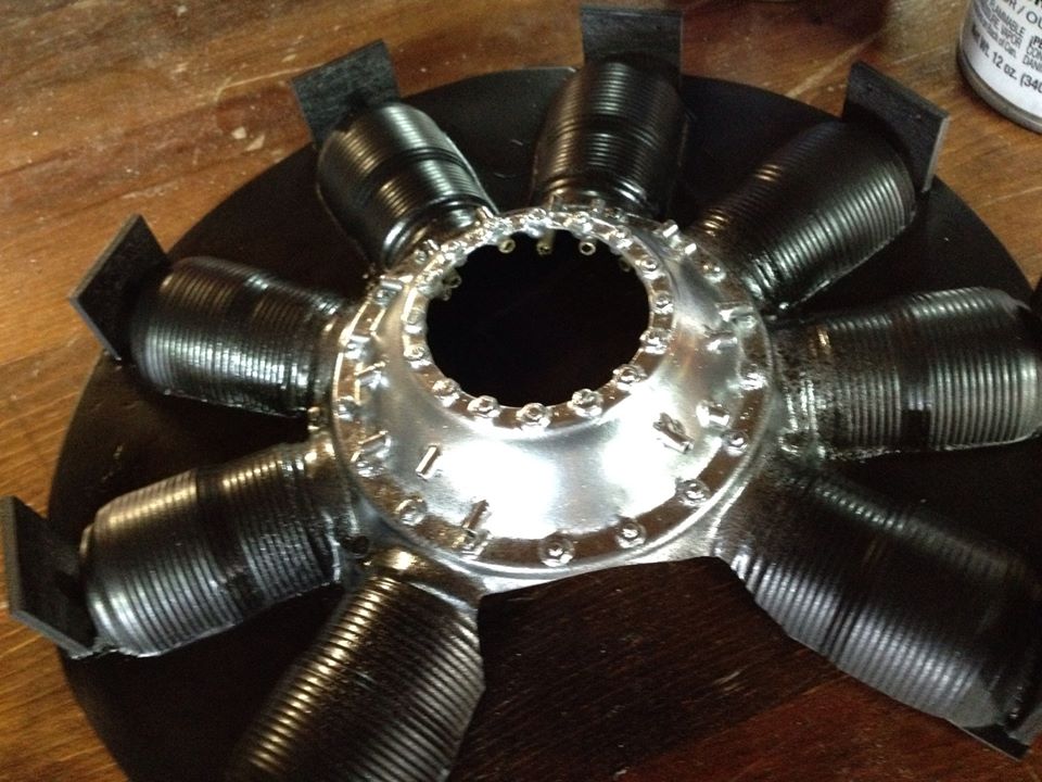
To start the paint job, I begin with a coat of metallic silver from Décor. This paint is quick drying and it provides an actual metallic nearly chrome look to the half. I like utilizing this brilliant coat as the primary layer which I’ll construct the weathering coats onto later within the course of.
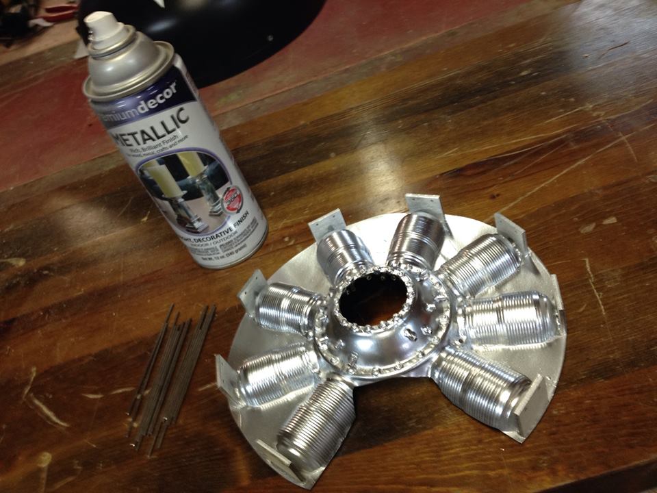
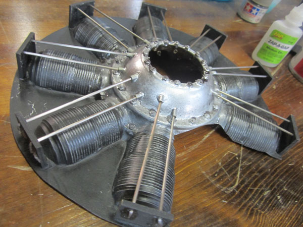
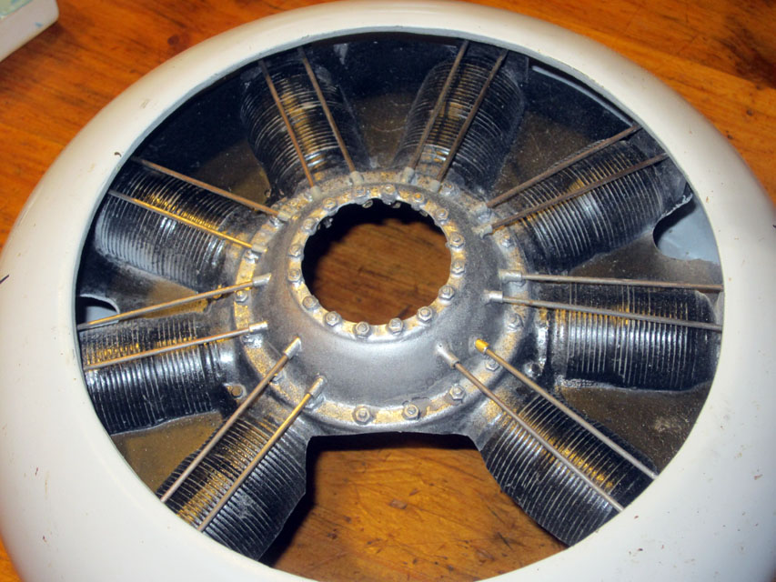
The paint actually makes all of the bits and items come collectively for a scale look. The 16 pushrods are made out of items of 1/16 inch welding wire.
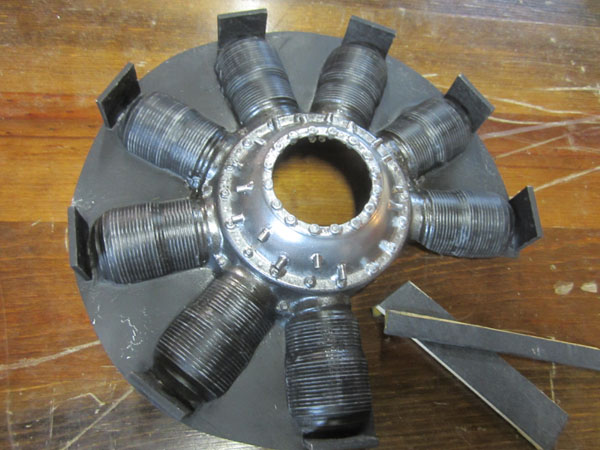
So right here the cylinders, and the again webbing have been spray painted flat black. I’ve discovered that there isn’t any must rigorously masks off the engine case whereas spraying the cylinders. Once more right here I take advantage of Decor spray paint which dries in a short time and is gasoline proof when dry.
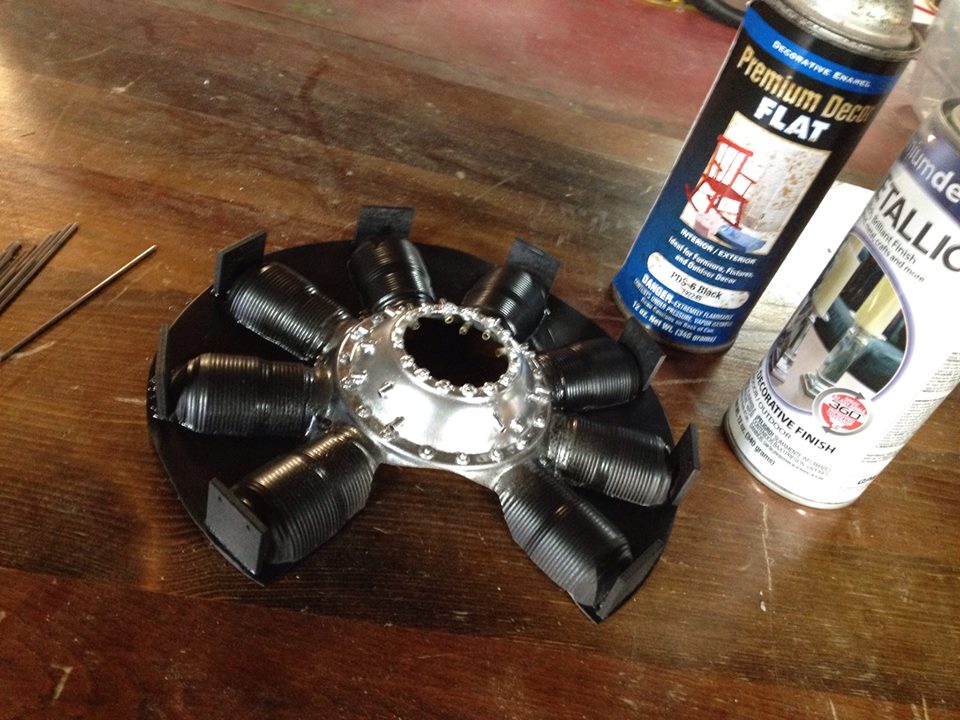
As you’ll be able to see, there’s a slight quantity of over spray on the perimeters of the crankcase, and that’s what we would like. Extra detailing and weathering shall be added to the engine to assist carry out the finer element and total realism a scale mannequin requires.
The following step is so as to add the pushrods. For the Sopwith Camel, I need a extra “used” look.
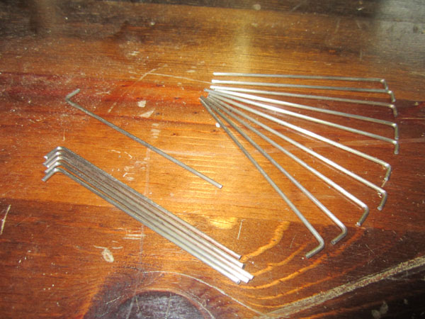
Right here above, now we have the 16 pushrod wires for the rotary engine. I used 1/16 inch welding wire and sanded them easy and clear. They has a pure metallic end so no portray is required. I additionally bent one finish 90 levels. The size is about 1/4 inch.

Earlier than putting in the pushrods, I took some 320 grit sandpaper and glued it to some wooden to kind sanding sticks. A large one for the highest of the cylinder and a slim one for the bottom. As you’ll be able to see, by rigorously sanding away the black paint, you expose the underlying silver and grey colours. This provides depth and kills among the shine of the black paint.
As with every part else about scale modeling and weathering, it takes a delicate contact. Don’t get heavy handed as you’ll solely make the silver traces (tops of the cooling fins), wider.
After sanding the fins, I’m going across the engine case and apply a really skinny layer of watered down acrylic black to all the small print. When dry, this black will being out the floor particulars.
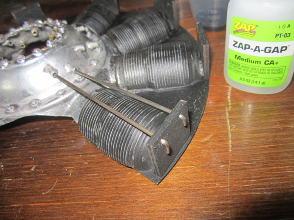
Right here you see two of the pushrod wires inserted into the wooden information plate and inserted into the brass bushing tubes on the crankcase. Just a little ZAP will maintain them in place. These high plates shall be coated over by the lip of the engine cowling and never seen.
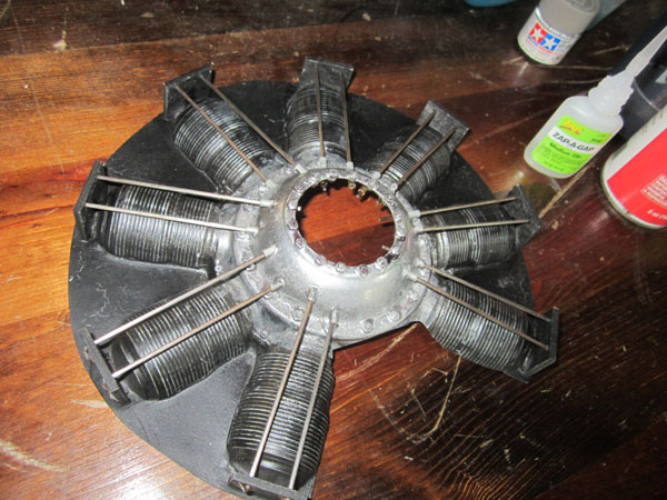
Right here all of the pushrods are in place. They’re glued on the high bent ends in addition to contained in the bushing tubes from the within of the engine molding.
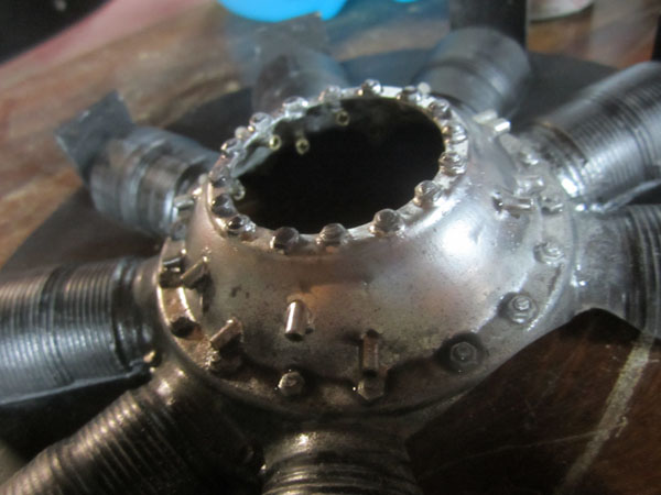
Subsequent I mist a really mild coat of sunshine grey over the chrome silver base coloration of the crankcase and let dry. I additionally use a skinny brush and add a grey wash to flat areas and in corners the place the actual full-size engine would collect mud and oil residue.
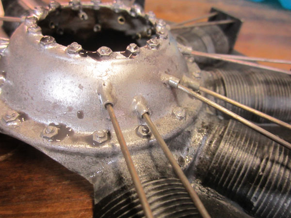
Right here you see the grey and black wash nonetheless puddled round among the nuts and screws across the engine and the bottom of the cylinders. Now let it dry. You may velocity the method with a warmth gun, however I discover that letting the washes evaporate naturally produces the perfect wanting staining.
The over all mission took solely about 10 hours and unfold over just a few days, that’s no time in any respect. I lastly determined to connect the molded engine to the within of the engine cowling. That is the standard technique to affixing it to a mannequin, however if in case you have the room, you may also set up standoffs to the firewall across the G38 and fasten the dummy rotary that manner. Right here’s how I did it.
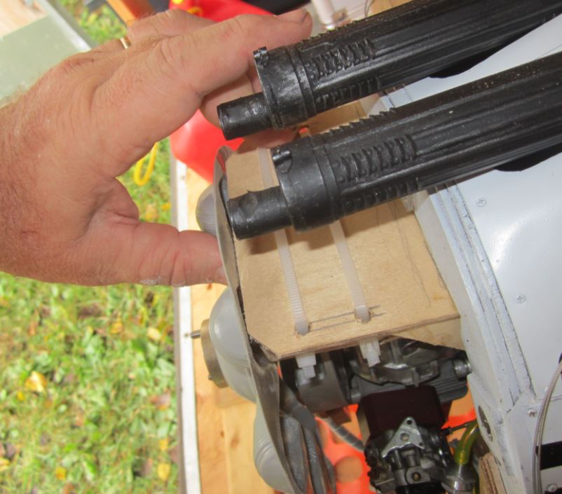
You’ll discover the wooden information plates I put in above every cylinder. These each help the pushrod wire ends and, give glorious attachment factors for the molding to be glued to the within of the engine cowling.
After sanding the paint off of the perimeters of the information plates, set the dummy engine in place over the mannequin’s actual engine and you then reattach the engine cowling. Ensure the dummy engine is centered across the prop hub and that nothing is available in contact with the G38 when the propeller shaft is turned. Now tack glue a few the information plates to the within of the cowling utilizing Thick Zap and kicker. Bear in mind, earlier than making use of any glue, it is essential to scrub off the inside floor of the cowling to make sure a powerful glue bond. I take advantage of MEK to take away all of the paint and primer from the inside floor of the fiberglass cowling.
After the glue units, tack glue a pair extra plates to the within of the cowling. Upon getting three or 4 plates glued in place, you’ll be able to take away the cowling.

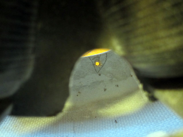
Right here’s a detailed up of one of many plates glued to the cowling. End gluing the remainder of the information plates in place being positive to construct up a powerful fillet across the information plates.

After all of the attachment factors have been secured, you should definitely make some openings within the webs between the cylinders. These are to get to any screws or different attachment factors for securing your engine cowling in place.
All you want is a gap giant sufficient to suit a screwdriver . With my magnetically secured cowling, I additionally put in two screws to stop the cowling from rotating as a result of engine vibration. The screws undergo the rear plywood cowling ring and thread into laborious factors within the entrance of the firewall.
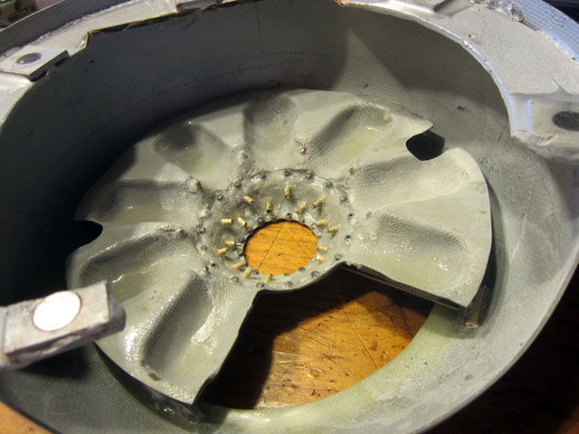
Right here you see the bottom of the dummy engine. Discover that there’s loads of area across the dummy engine for airflow to chill the engine. A lot of the airflow shall be by the big opening simply in entrance of the cylinder. Additionally if there is a hole between the cowling and any of the plates, (as proven right here to the precise), add a scrap of lite ply to fill within the area. Use loads of Zap and kicker.
Reinstall the engine cowling and test the clearances across the mannequin’s engine. Attempt to have at the very least 1/8 inch throughout. When every part traces up correctly, take away the engine another time and provides it just a few mild coats of honey coloured clear Urethane spray end. It will seal the wooden information plates and coat the pushrods in order that they don’t corrode. Additionally the colour give the engine a semi moist seem like it simply ran and is roofed with caster oil.
So, that’s it! The molded fiberglass dummy rotary engine from Balsa USA is a superb start line for any spherical nostril airplane. It actually is quite a bit much less work than scratch constructing your individual WW I cover-up. After a few flight, test the clearances between the size engine and the prop hub. If something is rubbing, use a Dremel Moto-Software and grind away any interference areas to extend the clearance. Additionally take note of how your engine runs. If it appears to be operating hotter than earlier than, regulate the carb, to richen the highest finish a bit. And recheck the idle transition. Have enjoyable!
TEXT & PHOTOS BY GERRY YARRISH


